London Midland and Scottish Railway Searchlight Signals
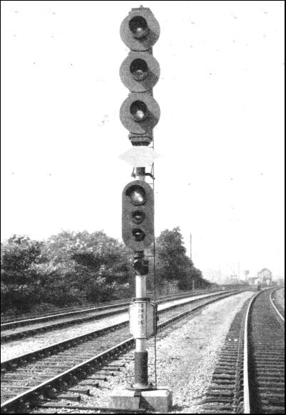
LMS searchlight junction signal
The
London Midland and Scottish Railway used colour light signals in
several
places. Installations after 1932 used the multi lamp type of signals similar to the
Southern Railway but initially in 1932 the LMS uniquely used a complex system of speed
signalling with searchlight signals on the London suburban lines to Watford and Upminster (the 'New Lines' signalling) as
well as a four mile section of 4-track main line at Mirfield (the 'Mirfield' signalling).
The
signals are capable of displaying up to five main aspects for high
speed:-
- Clear - proceed
- Advance Caution - the
next three blocks are clear
- Preliminary Caution - the next two blocks
are clear
- Caution - the next block is clear but
be prepared to stop at the next signal
- Stop
Junction signals can
additionally signal medium speed aspects for Medium Clear, Medium Preliminary Caution
and Medium Caution. Additional low speed indications for Call On and Take
Siding (Slow Clear) could also be provided. Stop signals with
inline heads were absolute and not to be passed at danger whereas Repeater signals with staggered
bottom heads were Stop and Proceed when at danger.
While
this signalling was installed initially by the LMS in 1932
it continued in use at Mirfield until 1970 with slight modifications and in North London until 1988. The configurations in the SC1 and shown below cover the period 1937-1988.
The
SC1 can be configured for individual searchlight heads in order to
operate these signals by
setting CV38=8 (standard accessory protocol) or CV38=129 (extended
accessory protocol). Complete masts can be configured by the use of
CV38=136 (two home, stop or repeater signals) or CV38=137 (one junction
signal) or the user defined settings for
CV38=135 can be used if required.
LMS signal masts are controlled according to the
following
tables:-
LMS 5-aspect Home searchlight signal operation table for CV38=8
|
Base
state
|
Base+1
state
|
Base+2
State
|
Base+3
State
|
Aspect
|
|
Reverse
|
Normal
|
Reverse
|
Normal
|
Red Red
|
|
Normal
|
Reverse
|
Normal
|
Normal
|
Green
|
|
Reverse
|
Reverse
|
Normal
|
Normal
|
Yellow
|
|
Reverse
|
Reverse
|
Normal
|
Reverse
|
Yellow Yellow
|
|
Normal
|
Reverse
|
Normal
|
Reverse
|
Yellow Green
|
LMS 3-aspect Call-On searchlight signal operation table for CV38=8
|
Base
state
|
Base+1
state
|
Base+2
State
|
Base+3
State
|
Aspect
|
|
Reverse
|
Normal
|
Reverse
|
Normal
|
Red Red
|
|
Normal
|
Reverse
|
Normal
|
Normal
|
Green
|
|
Reverse
|
Reverse
|
Normal
|
Normal
|
Yellow
|
|
Reverse
|
Normal
|
Normal
|
Reverse
|
Red Mini Yellow
|
LMS searchlight signal operation table for CV38=136 or CV38=137
|
Aspect description
|
Aspect
number
|
Junction
Aspect display
|
Stop/Repeater
aspect display
|
|
Stop
|
0
|
Red
Dark
Red
Red
|
(Dark)
Red
Red
|
|
Stop and Proceed
|
0
|
Red
Dark
Red
Red
|
(Dark)
Red
Red
|
|
Permissive
|
2
|
Red
Dark
Red
Small Yellow
|
-
Red
Small Yellow
|
|
Take Siding
|
1
|
Red
Dark
Red
Small Green
|
-
Red
Small Green
|
|
Clear
|
15
|
Green
Dark
Red
Red
|
(Dark)
Green
Dark
|
|
Approach
|
10
|
Yellow
Dark
Red
Red
|
(Dark)
Yellow
Dark
|
|
Preliminary approach
|
11
|
Yellow
Yellow
Red
Red
|
Yellow
Yellow
Dark
|
|
Advance Approach
|
12
|
Yellow
Green
Red
Red
|
Yellow
Green
Dark
|
|
Medium Clear
|
9
|
Red
Dark
Green
Red
|
-
-
-
|
|
Medium Preliminary Approach
|
6
|
Red
Yellow
Yellow
Red
|
-
-
-
|
|
Medium Approach
|
5
|
Red
Dark
Yellow
Red
|
-
-
-
|
|
Unlit
|
16
|
Dark
Dark
Dark
Dark
|
(Dark)
Dark
Dark
|
*Lamps shown as (Dark) are not present on 3-aspect signals
LMS searchlight signal wiring diagrams
2x 3-aspect, 4-aspect or 5-aspect stop or repeater signal wiring diagram
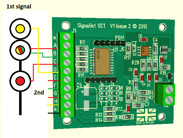
* Note that for a 3-aspect signal the top yellow lamp is not required
2x 3-aspect stop signal with call-on wiring diagram
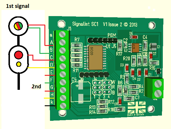
5-aspect junction searchlight wiring diagram
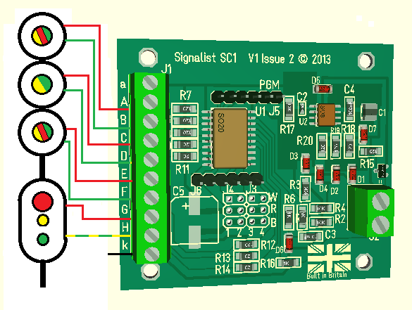
*Note that output H can either drive the Yellow Call on lamp or the Green take siding lamp but not both.
4-aspect junction searchlight wiring diagram
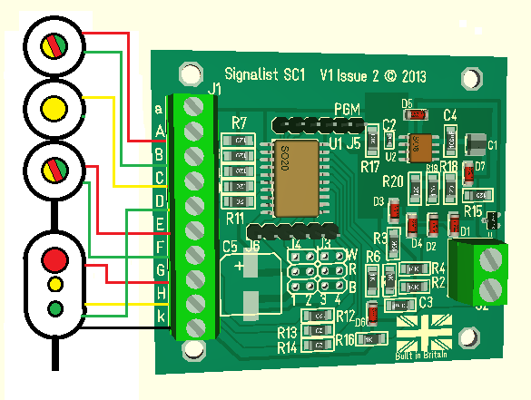
The following CV38 settings are possible:-
- CV38=8 - Any configuration (standard accessory protocol)
- CV38=136 - Two stop or repeater signals (extended accesory protocol)
- CV38=137- One Junction signal with call on or take siding (extended accesory protocol)
For other configurations use CV38=135 and create a user defined definition.
In
JMRI use DCC Signal Mast Decoder for CV38=135, CV38=138 and CV38=137.
For
CV38=8 in general use Double Output for the upper heads and Triple
Output for the bottom head, Single Output can be used for any heads
that can just display a single colour or dark. Visit the
JMRI LMS-1932 signal system to see the
available mast types.
Website design by Paul Harman © 2013


